Simulations and FEM of Topside Lift System Pioneering Spirit
The Challenge
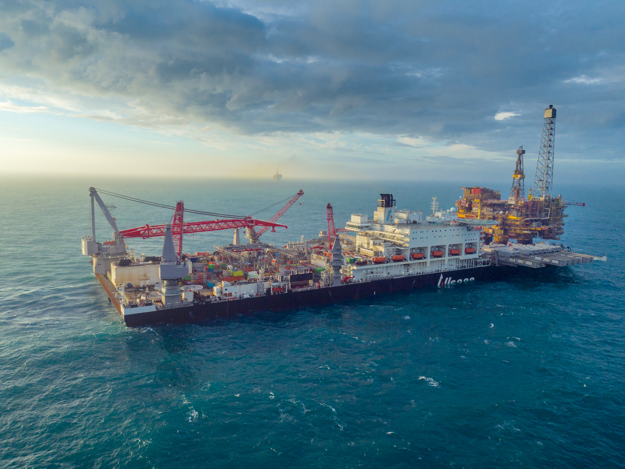
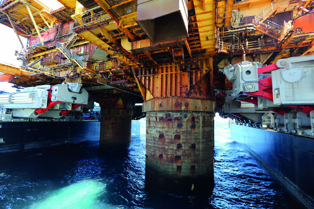
The development of the pioneering spirit was a first of many things. The vessel's size was unprecedented and the conceptual idea for a single Topside Lift System (TLS) revolutionary. As such, the main challenge was getting this to work.
The TLS was designed to lift topsides up to 48.000MT in one single lift, while the vessel was subject to the dynamic movements at sea. In order to achieve this, the active hydraulic system needed to be capable to compensate for external motion and to fast lift the topsides. At the same time the structural components would need to support the topside weight under these dynamic loads.
HVR Engineering was involved with the development of this impressive TLS via simulations of the system and with FE calculations of the main structural components.
Setting up a simulation model
The first simulation model was developed in the conceptual phase. As with all the simulation models that followed, it was used to verify conceptual designs on feasibility. The model focused initially on the components, parameters and setup of the TLS when connected to the topside.
After the first conceptual phases the simulation model was expanded to also include the behavior of the system during the connecting phase where the hydraulic clamps are positioned and clamped, and the fast-lift phase where the topside is lifted from the substructure in a matter of seconds.
Over the span of several years the model has been expanded and adjusted to the latest design changes and verification simulations used to optimize the system and simulate the behavior.
The final model included, amongst others, the following elements:
- Electrical drive system of X and Y directions
- Vessel 6DOF model
- Topside 6DOF model
- Ballast tank control model
- Lifting Beam model incl. loads on support and to topside
- Hinge geometry incl. lever and clamp
- Control model for trigger lift
- Hydraulic model incl. active motion compensation
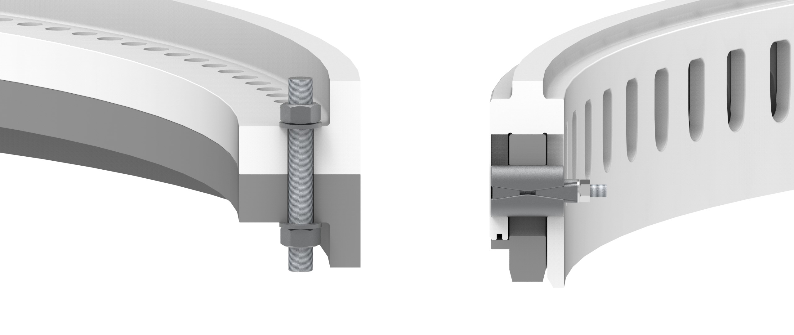
Finite Element Analysis
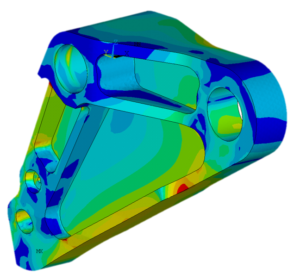
The main structural components of the TLS are the lifting beams, levers and pipe clamps. To optimize the design, reduce weights, but at the same time guarantee structural integrity, HVR Engineering assisted via FEM, fatigue, and buckling analysis.
All components were modelled in 3D in ANSYS and non-linear and dynamic analysis was applied. The main goal initially were structural checks on preliminary designs. When the project progressed, the work also comprised component weight optimization and redesign of various components. Design iterations were discussed together with the client and verified via the 3D FE models.
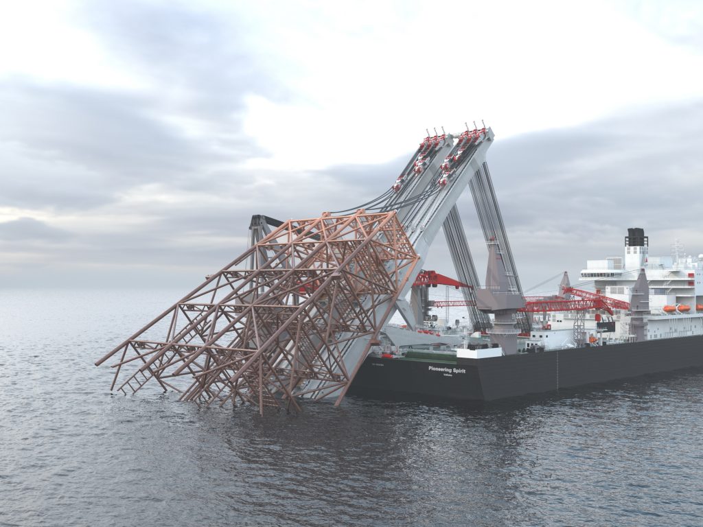
Jacket Lift System
The second main system on the Pioneering Spirit used for decommissioning is the Jacket Lift System (JLS). This system is designed to lift a complete jacket of the seabed. HVR Engineering also supported the client with this development by:
- Simulation models to evaluate the behavior of the JLS, including the behavior of the catenaries and a detailed model of the hoist system with each individual reeve.
- Supporting the development of the hydraulic and control system.
- FE calculations for the lifting beams.
What we can do for you
Projects like these are pushing the envelope and are projects we enjoy working on. We can support with the development of innovative dynamic controlled systems via simulation models and FEM. Want to know more? Have a look at our other projects or get in touch!